.png)
On a congested slab, the method itself is rarely your concern. What matters is simple: is the read accurate, can you core where planned, and where exactly the layout sits on the concrete. Everything else is secondary.
Digital concrete xray is often described as “more accurate,” but that doesn’t come down to the equipment alone. It comes from what happens after the exposure is taken. Rather than comparing methods at a high level, this walkthrough focuses on the post-processing stage of a digital xray job — step by step — so you can see how the final layout is actually established.
It’s also worth clarifying why this process can be shown so directly. With GPR, much of the outcome depends on real-time interpretation: reading signal responses, identifying patterns, and making informed judgments about what those patterns represent. That process is valid, but it largely happens in the technician’s analysis.
Digital xray works differently. It produces a direct radiographic image of the slab, similar in principle to medical imaging. The technician is interpreting visible conditions within that image, not translating signal data into probable objects. Because of that, the process — from capture to mark-out — can be reviewed in a transparent and straightforward way.
Here’s what that looks like, from the moment the image appears on the laptop to the final layout on the slab.
Post-processing refers to everything that happens between data capture and the final deliverable. That scope is broader than it sounds. It includes reviewing the image, confirming whether the planned core location is viable, transferring that information onto the slab, marking in a way the coring crew can rely on, and producing a report that the PM or engineer can confidently use for documentation.
The starting point for that process varies by method.
With GPR, the antenna generates a signal that is interpreted in real time. What appears on the screen are hyperbolic responses that only become “rebar,” “conduit,” or “PT cable” through technician judgment.
With traditional (film-based) xray, the exposure is captured onto film that must be developed, or onto a CR phosphor plate that is later scanned into a digital file. In both cases, there is no immediately viewable result when the shot is complete.
With digital concrete xray, the detector panel transfers the image directly to a laptop as soon as the exposure ends. The image is available for review within seconds.
All three methods ultimately deliver the same output: markings on the slab and a report for the client. What differs is the process between capture and that result.
On a digital concrete xray job, post-processing can be broken into three stages: the read, the marking, and the report.
With digital concrete xray, the image appears on the laptop immediately after the exposure. Within roughly 30 seconds to a few minutes of exposure time, the technician is reviewing a direct radiographic image of the embedded conditions — with no intermediate development or scanning steps required.
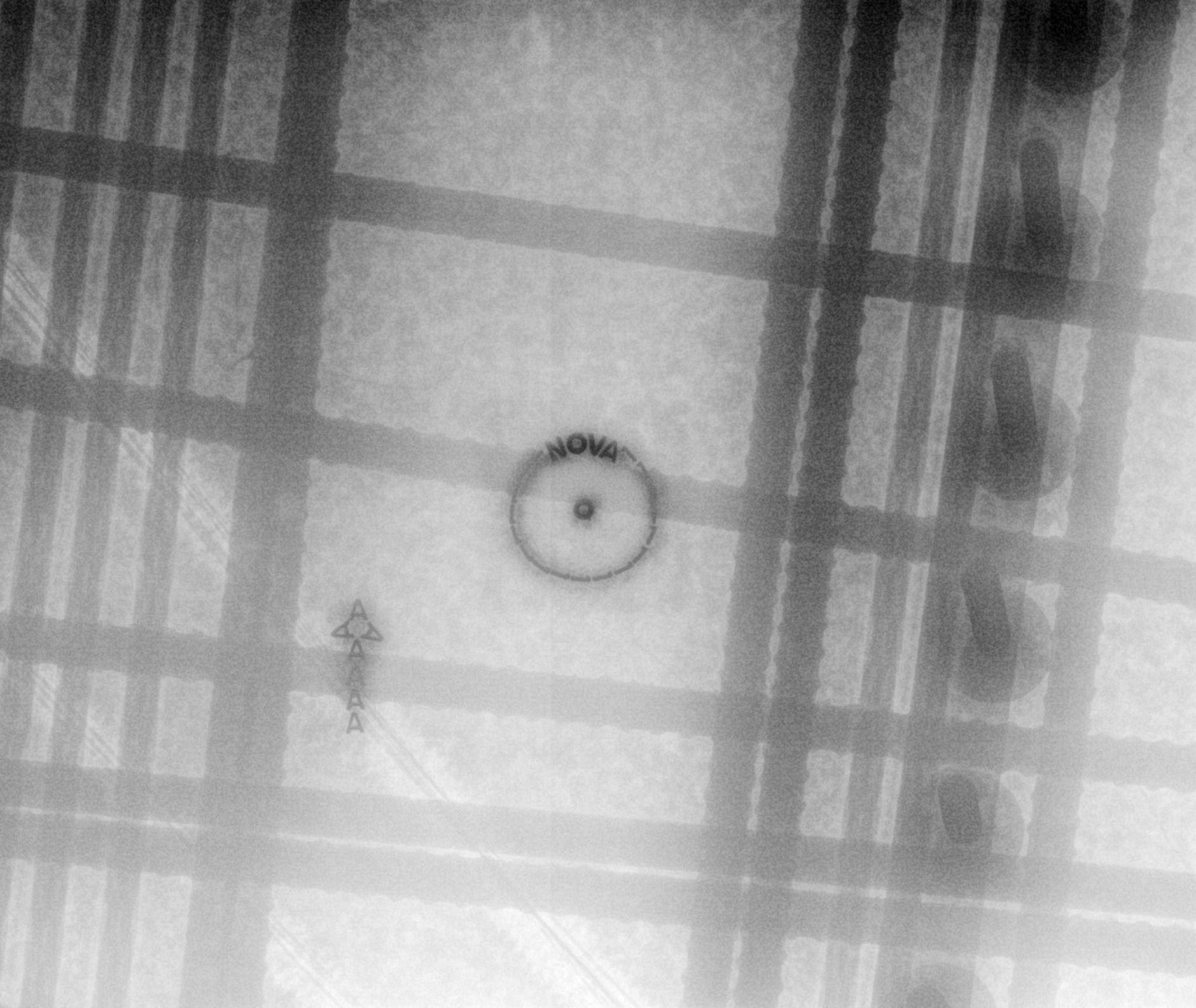
A brief note on what the image actually looks like, as this is often the part most people haven’t seen.
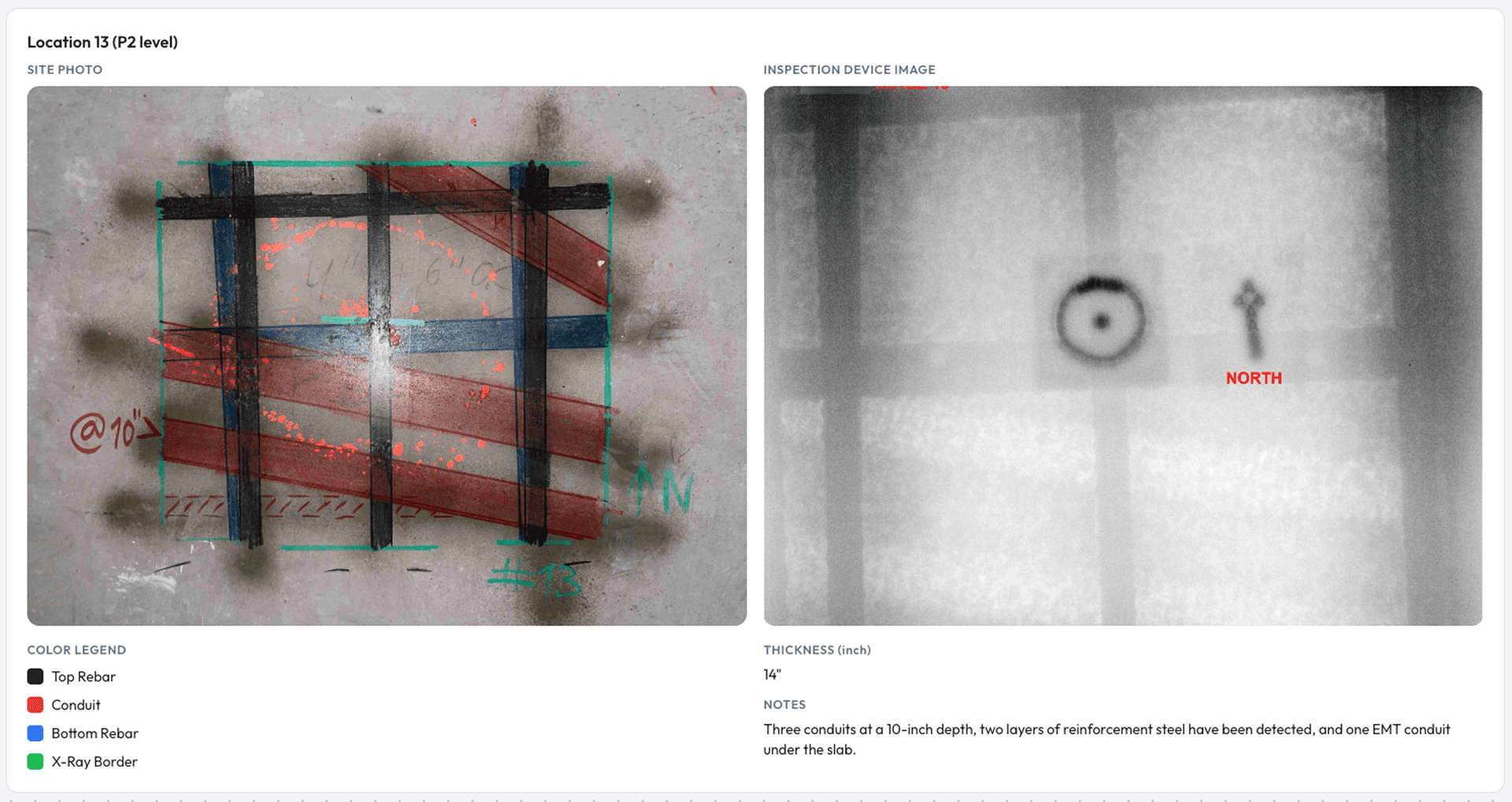
In a digital concrete xray image, embedded elements present in a way that is generally intuitive. Rebar appears as rebar. Conduit appears as conduit, and it is often possible to distinguish whether it is empty or contains wiring. Post-tension cables resemble rebar in form but typically show small, bright indications along their length due to the material within the sheathing.
Other conditions — voids, honeycombing, embedded plates, Nelson studs, and changes in slab thickness — are also directly visible. In most cases, if you are familiar with these elements in the field, you can recognize them in the image.
This is also where the distinction in method becomes more apparent.
With GPR, the technician is working from signal responses. Hyperbolic patterns must be interpreted and classified based on training and experience — determining what is likely rebar, conduit, or post-tension. This is skilled work, and when performed properly, it is effective.
However, the outcome depends on interpretation. The technician must identify all relevant responses within a dynamic and often challenging site environment. When elements are closely spaced, overlapping, or partially masked — such as a shallow conduit beneath a dense rebar mat — clarity can be reduced, and identification relies more heavily on judgment.
This is not a limitation unique to GPR, but rather a characteristic of any method based on signal interpretation.

Digital xray is often described in the industry as a definitive method, and the reason is straightforward. The image presents embedded conditions directly, rather than requiring signal-based interpretation.
For example, a thin conduit located beneath a dense rebar mat remains visible because the image reflects the combined material differences through the slab. The technician is not resolving an ambiguous signal, but reviewing a visible condition.
As a result, the process shifts from interpretation toward recognition. The technician is identifying what is present in the image, rather than inferring what a pattern may represent. This reduces reliance on judgment at that stage and contributes to more consistent outcomes.
This is also why xray is often the preferred approach in congested slabs, where multiple elements overlap and the cost of missing one is high.

Before any marks are placed on the slab, the technician verifies whether the planned core location fits within the spacing shown on the image. This is why having the core size in advance is important.
If the spacing is sufficient, the location is confirmed. If not, the technician identifies the nearest viable position on the same image and adjusts the layout accordingly — before any coring equipment is mobilized.
This is the stage that is often least visible from the outside, but it is critical to the outcome.
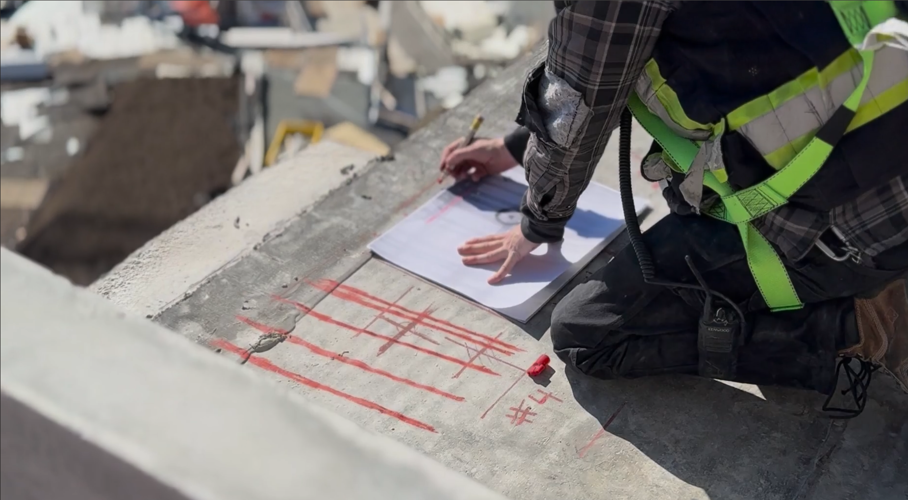
The objective is straightforward: transfer what is visible in the image onto the slab as accurately as possible. These markings become the working reference for the coring crew, often after the scanning team has left site.
Before the exposure is taken, the technician places a small physical reference label on the slab directly beneath the detector panel. That label appears on the xray image at a known position, creating a fixed reference between the slab and the image. From that point, all measurements are taken relative to that location.
There are two primary methods used to transfer that information onto the concrete.
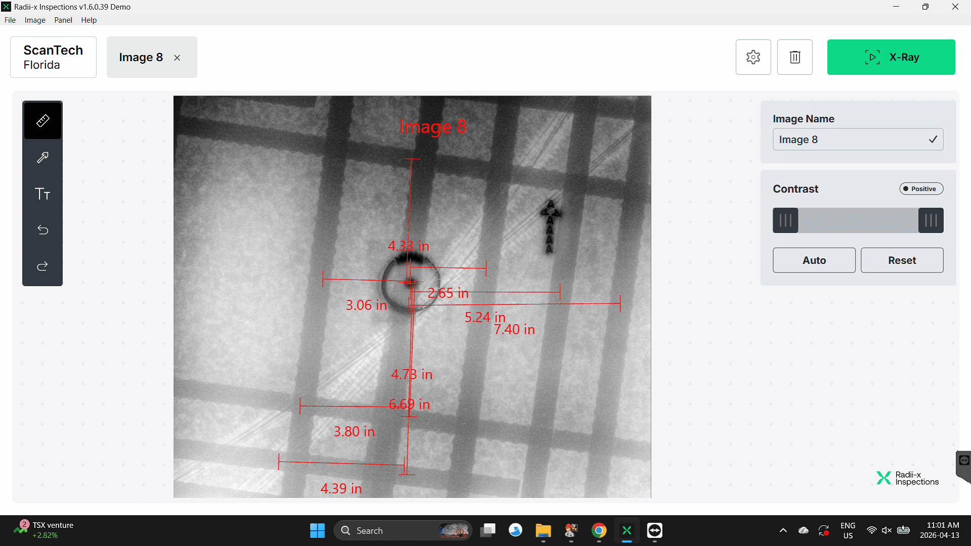
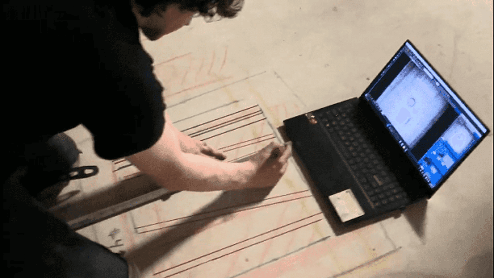
The first is manual measurement. At Nova, this is how most scans are completed. The technician uses measurement tools within the software to determine distances from the reference label to each identified element — rebar, conduit, post-tension cables. Those same measurements are then replicated directly on the slab using a tape measure and marking tools. The result is a layout that corresponds precisely to the image. This approach is efficient, accurate, and well suited to the majority of scanning conditions.
The second method is a full-scale (1:1) print overlay. On heavily congested slabs — where multiple layers of reinforcement, post-tension cables, and utilities overlap — manually measuring each element can become inefficient. In these cases, the xray image is printed at actual scale, aligned on the slab using the reference point, and the layout is transferred directly from the print. While slower per individual location, this method is often more efficient overall in dense conditions.
Both approaches achieve the same outcome: physical marks on the slab that correspond directly to the xray image. The choice between them depends on the complexity of the conditions being mapped. Simpler layouts are typically faster with manual measurement, while highly congested areas benefit from the print overlay approach. In all cases, the image remains the source of truth.
This stage also highlights a practical difference between digital and traditional film-based xray workflows. With film, the image must first be developed and then brought back to the slab before marking can occur. In many cases, marking is deferred or left to the contractor using the film as a reference. With digital systems, the image and slab are available simultaneously, allowing marking to be completed immediately on site. This is not a feature in itself, but a natural result of the workflow.
Marking is only useful if it is clear and unambiguous.

At Nova, a consistent, color-coded system is used across all projects:
Each mark is labeled in addition to being color-coded. This ensures that the coring crew can interpret the layout without relying on assumptions, even if the scanning team is no longer on site.
Marking practices vary across the industry. In some cases, markings may be present but lack clarity — inconsistent colors, minimal labeling, or unclear layout. The approach here is deliberate: when there is a clear image behind the layout, the markings should reflect that same level of clarity. This becomes especially important for the crews relying on those markings to execute the work.
Every scan should conclude with a complete report. Not simply an invoice with attached images, but a structured document.
This serves two purposes. First, the report is often forwarded to engineers or building management for review and approval. The quality of the report directly affects how the work is perceived.
Second, and more critically, the report becomes the formal record if an issue arises — such as damage to conduit or post-tension systems. It must clearly document what was identified and what was recommended. A vague report provides little value; a detailed report provides accountability and clarity.
A complete digital xray report at Nova includes:
The principle is straightforward: the image serves as the visual record, and the written findings confirm the interpretation. Together, they provide a complete and consistent account of the scan. This allows someone reviewing the report months later to understand the conditions without requiring further clarification.
When you hire a scanning contractor, the scanning itself is the visible part of the work. You see the setup, the controlled work area, the shots being taken, and the crew packing up when they’re done. It’s quick and easy to understand from the outside.
What you don’t see is everything that happens after the data is captured. The image still needs to be read correctly, the findings need to be transferred onto the slab in a way the coring crew can rely on, and the results need to be documented clearly in a report.
That’s what post-processing is. It’s the part of the job where accuracy is confirmed, decisions are made, and the information becomes usable in the field.
When it’s done properly, the coring crew can work with confidence, the engineer can review and approve without unnecessary back-and-forth, and the report remains clear and reliable long after the work is complete. When it’s not done well, that clarity breaks down, and mistakes are more likely to follow.
Related pages and articles: